Dynamic relief valve
## Copyright © EDF 2002 - 2026
## ThermoSysPro Version 4.2
This component model is documented in Sect. 13.13 of the ThermoSysPro book.
# Dynamic relief valve
Relief valves are used to limit the pressure in a system.
When the set pressure level is exceeded, the relief valve opens.
It closes again once the system pressure reaches the valve reseting pressure.s
Following assumptions are made:
- the fluid is subsonic and incompressible.
- the volume inside the valve is negligible, so that inertia is neglected.
## Modelica component model
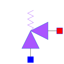
The equations mentioned below are implemented in the component *DynamicReliefValve*, located in the *WaterSteam.PressureLosses* sub-library.
This component has 2 connectors:
- C1: fluid inlet,
- C2: fluid outlet.

## Nomenclature
| Symbol| Description| Unit| Definition| Modelica name |
| :----------------------------------------------- | :--------------------------------------------------------------------------------------- | :------------------------------- | :------------------------------------- | :----------- |
| \\(A\_{\mathrm{i}}\\)| Clapper section at the inlet| \\(\mathrm{m}^{2}\\)|| A |
| \\(A\_{\mathrm{o}}\\)| Clapper section at the outlet| \\(\mathrm{m}^{2}\\)|| A2 |
| \\(C\_{\mathrm{v}}\\)| Flow coefficient of the valve| U.S. [USG/min]|| Cvmax |
| \\(D\\)| Valve damping| \\(-\\)|| D |
| \\(f\_{\mathrm{d}}\\)| Force acting on the clapper due to damping| \\(\mathrm{N}\\)|| Fd |
| \\(f\_{\mathrm{h}}\\)| Hydraulic force acting on the clapper| \\(\mathrm{N}\\)|| Fh |
| \\(f\_{\mathrm{s}}\\)| Force acting on the clapper due to the spring| \\(\mathrm{N}\\)|| Fr |
| \\(f\_{\mathrm{t}}\\)| Total force acting on the clapper| \\(\mathrm{N}\\)|| Ft |
| \\(f\_{\mathrm{w}}\\)| Force acting on the clapper due to the weight of the clapper| \\(\mathrm{N}\\)|| Fp |
| \\(h\\)| Fluid specific enthalpy | \\(\mathrm{J} / \mathrm{kg}\\)|| h |
| \\(h\_{\mathrm{c}}\\)| Valve height | \\(\mathrm{m}\\)| \\(h\_{\mathrm{c}}=z\_{\max }-z\_{\min }\\) | - |
| \\(K\_{\mathrm{e}}\\)| Valve spring stiffness| \\(\mathrm{N} / \mathrm{m}\\)|| Ke |
| \\(\dot{m}\\)| Fluid mass flow rate| \\(\mathrm{kg} / \mathrm{s}\\)|| Q |
| \\(M\\)| Valve mass| \\(\mathrm{kg}\\)|| m |
| \\(P\_{\mathrm{i}}\\)| Fluid pressure at the inlet| \\(\mathrm{Pa}\\)|| C1.P |
| \\(P\_{\mathrm{o}}\\)| Fluid pressure at the outlet| \\(\mathrm{Pa}\\)|| C2.P |
| \\(v\\)| Clapper velocity| \\(\mathrm{m} / \mathrm{s}\\)|| v |
| \\(z\\)| Clapper position| \\(\mathrm{m}\\)|| z |
| \\(z\_{\min }\\)| Clapper minimum position \(valve fully closed\)| \\(\mathrm{m}\\)|| z_min |
| \\(z\_{\max }\\)| Clapper maximum position \(valve fully open\)| \\(\mathrm{m}\\)|| z_max |
| \\(\delta\\)| Difference between the free spring length and the spring length when the valve is closed | \\(\mathrm{m}\\)|| - |
| \\(\Delta P\\)| Pressure loss of the fluid between the valve inlet and outlet| \\(\mathrm{Pa}\\)| \\(P\_{\mathrm{i}}-P\_{\mathrm{o}}\\)| deltaP |
| \\(\rho\\)| Fluid density| \\(\mathrm{kg} / \mathrm{m}^{3}\\) ||rho |
| \\(\rho\_{\text {water, } 60^{\circ} \mathrm{F}}\\) | Density of water at \\(60^{\circ} \mathrm{F}\left\(15.5556^{\circ} \mathrm{C}\right\) .\\)| \\(\mathrm{kg} / \mathrm{m}^{3}\\) || rho60F |
| \\(\Omega\\)| Valve position| \\(-\\)|| Ouv |
## Governing equations
### Static momentum balance equation
- Validity domain:
\\(\forall \dot{m}\\) and \\(C\_{\mathrm{v}} \geq 0\\). For \\(C\_{\mathrm{v}}=0, \Delta P\\) must be defined.
- Mathematical formulation:
$$\Delta P \cdot C\_{\mathrm{v}} \cdot\lvert C\_{\mathrm{v}}\rvert =1.732189 \times 10^{12} \cdot \frac{\dot{m} \cdot \lvert \dot{m} \rvert }{\rho \cdot \rho\_{\text {water, } 60^{\circ} F}}$$
- Comments:
This equation is the same as the control valve \\(C\_{\mathrm{v}}=f\_{v}\(\Omega\)\\) where \\(f\_{v}\\) is the valve characteristic. It is assumed that \\(\Omega=\frac{z-z\_{\min }}{z\_{\max }-z\_{\min }}\\).
### Clapper equation
- Validity domain:
\\( z\_{\min} \leq z \leq z\_{\max} \\)
- Mathematical formulation:
$$ M \cdot \frac{\mathrm{d} \nu}{\mathrm{d}t}=\left\{\begin{array}{l} f_{\mathrm{t}} \text{ if } z_{\min }<z<z_{\max } \\ f_{\mathrm{t}} \text{ if } z \leq z_{\min } \text{ and } f_{\mathrm{t}}>0 \\ f_{\mathrm{t}} \text{ if } z \geq z_{\max } \text{ and } f_{\mathrm{t}}<0 \\ 0 \text{ else }\end{array}\right.$$
$$ \nu =\left\{\begin{array}{l}\frac{\mathrm{d} z}{\mathrm{d} t} \text{ when } z_{\min }<z<z_{\max } \\ 0 \text{ when } z \leq z_{\min } \text{ or } z \geq z_{\max }\end{array}\right.$$
$$ f_{\mathrm{t}} = f_{\mathrm{w}}+f_{\mathrm{s}} +f_{\mathrm{d}}+ f_{\mathrm{h}} \\ f_{\mathrm{w}} = -M \cdot g \\ f_{\mathrm{d}} = -D \cdot \frac{\mathrm{d} z}{\mathrm{d} t} \\ f_{\mathrm{s}} = -K_{\mathrm{e}} \cdot (z - z_{\min} + \delta) \\ f_{\mathrm{h}} = P_{\mathrm{i}} \cdot A_{\mathrm{i}} - P_{\mathrm{o}} \cdot A_{\mathrm{o}}$$
- Comments:
The velocity and acceleration are set to zero when the clapper hits the mechanical stops. The equal sign is replaced by \\(\leq\\) or \\(\geq\\) in the transition conditions \\(z=z_{\min }\\) and \\(z=z_{\max }\\) because equal signs are not recognized by solvers to compare real values.
## References
El Hefni, Baligh and Bouskela, Daniel (2019). [Modeling and Simulation of Thermal Power Plants with ThermoSysPro](https://link.springer.com/book/10.1007/978-3-030-05105-1), sect. 13.1. Springer Nature Switzerland AG.
Author Daniel Bouskela
Generated at 2026-08-05T20:24:29Z by OpenModelicaOpenModelica 1.27.0 using
GenerateDoc.mos
 .ThermoSysPro.WaterSteam.PressureLosses.DynamicReliefValve