Switch valve
## Copyright © EDF 2002 - 2026
## ThermoSysPro Version 4.2
This component model is documented in Sect. 13.10 of the ThermoSysPro book.
# Switch valve
A switch valve has only two stable positions: fully open or fully closed.
When it is open, the fluid flows with a pressure loss. For ideal valves, this pressure loss is zero. When it is closed, the mass flow rate is zero (unless the valve is leaking).
Switch valves are usually controlled by a binary signal, like [control valves](modelica://ThermoSysPro.WaterSteam.PressureLosses.ControlValve). But only 0 and 1 are stable positions for the switch valve.
Following assumptions are made:
- the fluid is subsonic and incompressible.
- the volume inside the valve is negligible, and so is its inertia.
- the valve is assumed to switch positions instantly.
If the latter assumption is not valid, the [control valve](modelica://ThermoSysPro.WaterSteam.PressureLosses.ControlValve) should be used with an actuator modeling the continuous position switch.
## Modelica component model
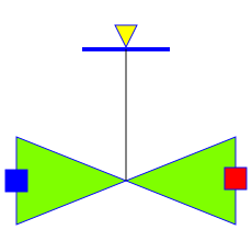
The equations mentioned below are implemented in the component *SwitchValve*, located in the *WaterSteam.PressureLosses* sub-library.
This component has 3 connectors:
- C1: fluid inlet,
- C2: fluid outlet,
- Ouv: valve opening.

## Nomenclature
| Symbol| Description| Unit| Definition| Modelica name |
| :----------------- | :---------------------------------------------------------- | :--------------------------- | :-------------------------------- | :----------- |
| \\(h\\)| Fluid specific enthalpy | \\(\mathrm{J} / \mathrm{kg}\\) || h |
| \\(P\_{\mathrm{i}}\\) | Fluid pressure at the valve inlet| \\(\mathrm{Pa}\\)|| C1.P |
| \\(P\_{\mathrm{o}}\\) | Fluid pressure at the valve outlet| \\(\mathrm{Pa}\\)|| C2.P |
| \\(\dot{m}\\)| Fluid mass flow rate| \\(\mathrm{kg} / \mathrm{s}\\) || Q |
| \\(\Delta P\\)| Pressure loss of the fluid between the inlet and the outlet | \\(\mathrm{Pa}\\)| \\(P\_{\mathrm{i}}-P\_{\mathrm{o}}\\) | deltaP |
| \\(\Lambda\\)| Friction pressure loss coefficient| \\(\mathrm{m}^{-4}\\)|| k |
| \\(\rho\\)| Fluid density| \\(\mathrm{kg} /^{3}\\)|| rho |
| \\(\Omega\\)| Valve position \(0 or 1\)| \\(-\\)|| Ouv.signal |
## Governing equations
### Static momentum balance equation
- Validity domain:
\\(\forall \dot{m}\\). For \\(\dot{m}=0, \Delta P\\) must be defined.
- Mathematical formulation:
$$ \left\{\begin{array}{l} \dot{m}=0 \; \text{if} \; \Omega=0 \\ \Delta P=\Lambda \cdot \frac{\dot{m} \cdot \lvert \dot{m}\rvert}{\rho} \; \text{if} \; \Omega=1 \end{array} \right.$$
- Comments:
This formulation switches dynamically when \\(\Omega\\) switches between 0 and 1. When \\(\Omega=0\\), the valve is fully closed, so the proper definition of \\(P_i\\) and \\(P_o\\) in the components adjacent to the valve should be checked.
## References
El Hefni, Baligh and Bouskela, Daniel (2019). [Modeling and Simulation of Thermal Power Plants with ThermoSysPro](https://link.springer.com/book/10.1007/978-3-030-05105-1), sect. 13.1. Springer Nature Switzerland AG.
Author Daniel Bouskela
Generated at 2026-08-05T20:24:29Z by OpenModelicaOpenModelica 1.27.0 using
GenerateDoc.mos
 .ThermoSysPro.WaterSteam.PressureLosses.SwitchValve